
Set up the overnight flow and return logging job
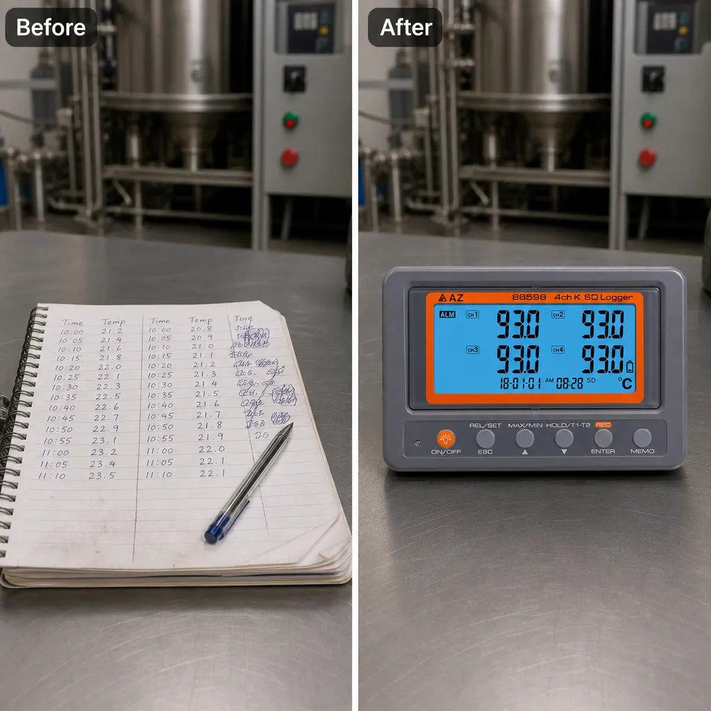
To learn how to log boiler flow and return temperatures overnight, connect suitable K-type probes to separate channels, position them consistently at the chosen flow and return points, set a sampling interval, and start recording before leaving the plant room. Keep the logger itself between 0°C and 50°C and below 80% humidity. Before departure, confirm that both displayed temperatures respond and appear plausible, then note which channel represents flow and which represents return so the two traces cannot be confused later.
The purpose of the overnight run is to preserve a sequence rather than one isolated measurement. A four-channel K-type thermometer data logger can record several locations during the same period, while its stated sampling rate is programmable from one second upwards. For a basic boiler comparison, two channels may be enough for flow and return. If the investigation also needs cylinder or ambient temperatures, the four available channels become relevant, but the documented package includes only two K-type thermocouple probes.
Choose useful points in the UK plant room
Select measurement points that answer a defined question about the boiler cycle. For the core comparison, use one point on the flow side and one on the return side. Keep both positions clearly labelled and avoid changing their location during the run. The listing does not state the construction or attachment method of the supplied probes, so do not assume they are designed to clip, strap or bond directly to a particular pipe. Check that their physical form suits the intended surface before planning the visit.
A four-channel arrangement can broaden the picture when compatible probes are available. Channels one and two might represent flow and return, while the remaining inputs could be reserved for other relevant temperature points. However, those extra locations should serve the diagnosis rather than merely fill channels. Write a short channel map before starting: for example, CH1 flow and CH2 return. If additional probes are used, record their positions just as precisely so every line in the resulting data has an unambiguous plant-room location.
Match the probes to the pipe surface and temperature
The instrument accepts K-type thermocouples and has a published measurement range of -200°C to 1370°C, with 0.1°C or °F resolution. That broad instrument range does not establish that every connected probe is suitable across the same temperatures. The supplied information gives no separate probe range, construction material or surface-attachment details. For boiler pipe logging, verify the usable limits and intended contact method of each probe rather than treating the logger’s headline range as a complete specification for the whole setup.
Surface contact also affects whether two channels provide a useful comparison. Apply the same considered attachment approach at both selected points, keep the sensing positions stable and route the leads so they are not pulling on the probes. The product facts do not include fixing accessories, so establish what will hold each sensor in place before arriving at the plant room. If stable, appropriate attachment cannot be confirmed for the supplied probes, obtain compatible K-type probes intended for the chosen measurement arrangement before attempting an unattended run.
Select an interval that captures boiler cycles
The logger supports programmable sampling from one second upwards, but the shortest available interval is not automatically the most useful overnight choice. Begin with the event you need to see: start-up, a heating period, cooling between calls for heat, or repeated cycling. Choose an interval that gives several readings across those changes without producing more detail than you can sensibly inspect. Record the selected interval in the job notes because it determines how closely the temperature sequence represents changes during the night.
Carry out a short observed trial in the plant room before committing to the full run. Start logging, allow the readings to develop, and check that the channel labels, units and interval are as intended. The display is listed as 47 by 104 mm, providing a place to inspect the active readings during setup. A trial does not replace the overnight record, but it can expose a reversed channel label, an inactive input or an unsuitable sensor position while there is still time to correct the arrangement.
Plan power and recording before leaving the logger
The stated power choices are AA batteries, which are included in the set, or a 9V adaptor, which is not included. Decide on the power arrangement before the overnight visit rather than discovering the missing adaptor in the plant room. The published facts do not give a battery-runtime figure, so they cannot establish that one set of batteries will cover a particular logging duration. If an adaptor is preferred, its required compatibility needs to be confirmed because the listing supplies no further adaptor specification.
The product is described as an SD card data logger, but the published information does not state the included storage media, card capacity, recording format or file-handling process. Confirm those points before relying on the logger for a customer record. Prepare the recording medium as required, start a short log and make sure the resulting information can be accessed through the workflow you intend to use. This check is especially important when the aim is to compare timestamps or retain evidence after leaving the plant room.
Use this plant-room departure checklist
Start with the measurement checklist: confirm that each connected sensor is a compatible K-type probe; verify that its form and limits suit the chosen surface; label CH1 as flow and CH2 as return; and document any additional channel locations. Check that both temperatures are visible and responsive, that °C or °F is set as intended, and that the programmed interval matches the boiler behaviour being investigated. Photographing or writing down the channel map can prevent uncertainty when the readings are examined later.
Then complete the environment and continuity checklist: position the instrument where the temperature remains within 0°C to 50°C and humidity remains below 80%; keep the logger separate from any location that would exceed those instrument limits; confirm the battery or compatible adaptor arrangement; and verify that recording has actually started. Finally, note the start time, planned collection time and selected interval. Do not leave the setup if a probe can move, the display suggests a failed input, or the recording and power arrangements remain uncertain.
Recognise specification gaps and avoid a poor match
This product may be a poor match if the job requires four simultaneous measurements straight from the supplied pack. Although the logger has four channels, the documented contents mention only two K-type thermocouple probes. Using flow, return, cylinder and ambient points together would therefore require two further compatible probes. It is also unsuitable to purchase on the assumption that a 9V adaptor is supplied, because the listing explicitly says it is not included. Include those missing parts when assessing the complete setup.
There are also limits on what the published information can support. The accuracy bullet is incomplete: it names accuracy but gives no numerical value. No calibration documentation is identified, and the supplied probe limits and attachment method are not stated. If the job requires a defined uncertainty, traceable documentation or a particular probe construction, obtain those details before purchase. The logger should also not be placed where its stated 0°C to 50°C operating range or below-80% humidity condition cannot be maintained.
Compare the overnight traces and decide the next check
When the logger is collected, first preserve the channel map and timing information with the recorded temperatures. Compare flow and return over the same timestamps rather than selecting unrelated high and low readings. Look at when both values rise, when they fall and whether the relationship repeats across more than one operating period. Keep the interpretation tied to the labelled measurement positions and the chosen interval; without those notes, even a detailed temperature file can be difficult to relate back to the plant-room arrangement.
The grounded next step is to decide whether two channels answer the question or whether the investigation genuinely needs all four. For flow and return only, the two documented included probes may cover the channel count, subject to probe suitability. For four locations, budget and prepare two additional compatible K-type probes, plus any appropriate attachment items and a confirmed power arrangement. Before relying on the results, resolve any requirement for stated accuracy or calibration documentation that is not covered by the published product information.