
Decide whether temperature logging suits the heating fault
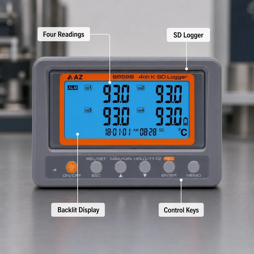
Use a temperature data logger for heating system fault finding when the important question is not simply how hot something is now, but how several temperatures change during an operating cycle. A four-channel K-type instrument can record up to four connected measurement points at the same time, while a programmable sampling rate starting at one second lets you choose how closely to follow the event. Before buying, identify the exact points you need to monitor, confirm that suitable K-type probes exist for them and allow for the fact that this package lists two probes rather than four.
This approach is most relevant when a heating system behaves differently over time and one reading in the boiler cupboard cannot show the sequence. Simultaneous channels help avoid the timing problem created by moving one meter between locations. However, the logger does not diagnose the cause by itself. It records temperatures for comparison, so the usefulness of the result still depends on sensible probe positions, a suitable sampling interval and a clear note of what the heating system was asked to do during the recorded period.
Set the measurement job in the boiler cupboard or plant room
Begin with a written question rather than attaching probes wherever there is space. In a domestic boiler cupboard, the question might concern whether two accessible points warm together, whether one point changes later than another or whether a temperature repeatedly rises and falls. A light-commercial plant room may require a longer view across several operating periods. Turn that question into a small set of named measurement locations, then decide whether two, three or four simultaneous channels are genuinely needed. This prevents a large file of readings from becoming a collection of lines with no defined purpose.
Keep a simple site note linking each numbered logger channel to its actual location. Labels such as Channel 1 and Channel 2 are not enough once the equipment has been removed, particularly if several traces look similar. Record the start time and any relevant control change in the same note. The documented 47 x 104 mm LCD can support checks at the instrument, but the lasting value of the exercise comes from knowing what each recorded channel represented and what was happening in the heating system at that point.
Check channel count, probe count and probe suitability
The instrument is described as a four-channel K-type thermometer and SD card datalogger, but the package title states that two K-thermocouple probes are supplied. That distinction matters. A two-point investigation may be possible with the listed contents, whereas a four-point plan requires two additional compatible probes. Do not assume that four sockets mean four probes are in the box. Work out the full measurement layout first, count the probes required and confirm compatibility before treating this as a complete four-point heating diagnostic setup.
The published information does not state the construction, attachment method or individual usable range of the supplied probes. It therefore cannot establish whether they are appropriate for a particular pipe surface, cylinder location or ambient position. The instrument’s broad stated K-type range of -200 to 1370°C is not proof that every connected probe can cover that entire range or suit every surface. Check the intended probe form and its documented limits separately, and make sure the attachment method will keep the sensing point in a consistent position throughout the logging period.
Choose a sampling interval that matches the heating cycle
The sampling rate is programmable from one second upwards. The shortest available interval can be useful when a rapid change is the subject of the investigation, but it should not be selected automatically. For a longer heating cycle, a less frequent reading may still show the important pattern while producing a more manageable record. Decide what event you need to see, estimate how quickly it changes and select an interval that gives several readings across that event rather than relying on one value before it and another afterwards.
Run a short observed check in the boiler cupboard before leaving the logger to record for longer. Confirm that every intended channel responds and that its displayed value is plausible for its location. Then note the selected interval and the start time. The product is described as an SD card datalogger, but the public information does not specify the card requirement, file format, storage capacity or data-handling procedure. Verify those details and the availability of any required storage media before planning an unattended session or promising a particular reporting workflow.
Keep the instrument within its stated site conditions
Separate the temperature at the probe from the conditions around the logger itself. The stated K-type measurement range is -200 to 1370°C, with 0.1°C or °F resolution, but the instrument’s stated operating environment is much narrower: 0 to 50°C and below 80% humidity. In a boiler cupboard or plant room, position the main unit where those operating limits can be maintained while the connected probes reach the selected measurement points. Do not interpret the probe measurement range as permission to expose the logger body to the same conditions.
Storage limits are stated as -20 to 50°C and below 90% humidity. Those figures are relevant when the instrument is kept in a van, workshop or storeroom between jobs, while the operating figures govern conditions during measurement. Power also needs a deliberate plan. AA batteries are included in the set, and a 9V adaptor is an alternative, but the adaptor is not included. The published details do not state battery runtime or the required adaptor specification, so neither option should be assumed suitable for a planned duration without further checking.
Recognise the evidence gaps before relying on the readings
The product information states a resolution of 0.1°C or °F, but its accuracy line does not provide a numerical accuracy value. Resolution describes the displayed step size; it does not, by itself, establish how close a reading is to the true temperature. The public details also do not mention calibration documentation. If your heating report depends on a defined level of measurement accuracy or traceability, obtain the missing information before purchase and decide whether it meets the standard required for that particular job.
This logger is also a poor match when the measurement point cannot accept an appropriate K-type probe, when the main instrument would have to sit outside its stated operating conditions or when the job needs more probes than you have confirmed. It should not be chosen solely because its overall temperature range is wide. Heating fault finding usually depends more on suitable probes, stable placement, concurrent channels and interpretable timing than on the extremes of the instrument range. A single-channel meter may remain adequate when only one point and one moment need checking.
Use this boiler-cupboard setup checklist before recording
Start with the measurement plan: write down the heating behaviour you want to examine, name each location and assign it to a channel. Count the required probes, remembering that the instrument offers four channels but the listed set includes two K-thermocouple probes. Confirm that every probe is compatible and suitable for its intended surface or ambient position. Check that the logger body can remain between 0 and 50°C and below 80% humidity, and choose a stable position where the display can be inspected without pulling on the probe leads.
Next, choose a sampling interval from the programmable range of one second upwards and record that choice in the job notes. Decide between the included AA batteries and a separately sourced, verified 9V adaptor, taking account of the intended recording period without assuming an undocumented runtime. Confirm any SD card requirements before attending site. Finally, start a short trial, inspect all active channels on the 47 x 104 mm LCD, check that each channel label matches the written location and note the exact time at which the main logging period begins.
Compare the temperature timeline and choose the next inspection
Once the recording period is complete, compare channels by time rather than looking only at their highest and lowest values. Mark when each temperature begins to change, how quickly it moves, whether another point follows after a delay and whether the same relationship repeats. Also compare those changes with the written notes from the boiler cupboard or plant room. A useful record should help narrow the next inspection; it should not be treated as automatic proof of a component fault without the wider system context.
The practical next step is to finalise one real measurement plan and check it against the documented facts. If it needs no more than four simultaneous K-type channels, can use suitable verified probes, fits the programmable sampling arrangement and keeps the instrument within its operating environment, this type of logger may suit the job. Before committing, resolve the incomplete accuracy information, probe suitability, SD card requirements and power details. Include any extra probes and the optional adaptor in the complete setup rather than comparing the logger price alone.